The distinguishing feature of EdrawMax Online is the representation of the p&id diagram.

It starts from the water inlets, covers the whole process till the filtered water leaves the plant. It shows the design with the piping and associated parts of a physical process flow. This is a wastewater treatment plant P&ID drawing of a processing plan that includes the piping and process equipment. The schematic diagram of the refrigerator includes all the equipment, including the expansion water tank, plate heat exchanger, return cylinder, etc., and other supporting equipment and their connection methods.Įxample 3: Wastewater Treatment Plant PID Since most of the equipment and installation details are concealed, this diagram helps identify the faults and bugs for quick repair and maintenance. Such diagrams are helpful in the design and installation process and support the system throughout its lifespan. This P&ID diagram is about a central air conditioning system complete with equipment, connections, and process description. Following are some examples of the p&id diagram for further reference. P&id diagram drawing can be a complex process however, with proper tools and skills, you can make the process simpler. Also, this program allows you to export your document in several famous formats like PDF, JPEG, Visio, Powerpoint, and others. Here is the simple method to create P&ID diagrams in EdrawMax Online. It is a comprehensive program with well-equipped symbol and template libraries for creating p&id diagrams among 280+ other drawing types.

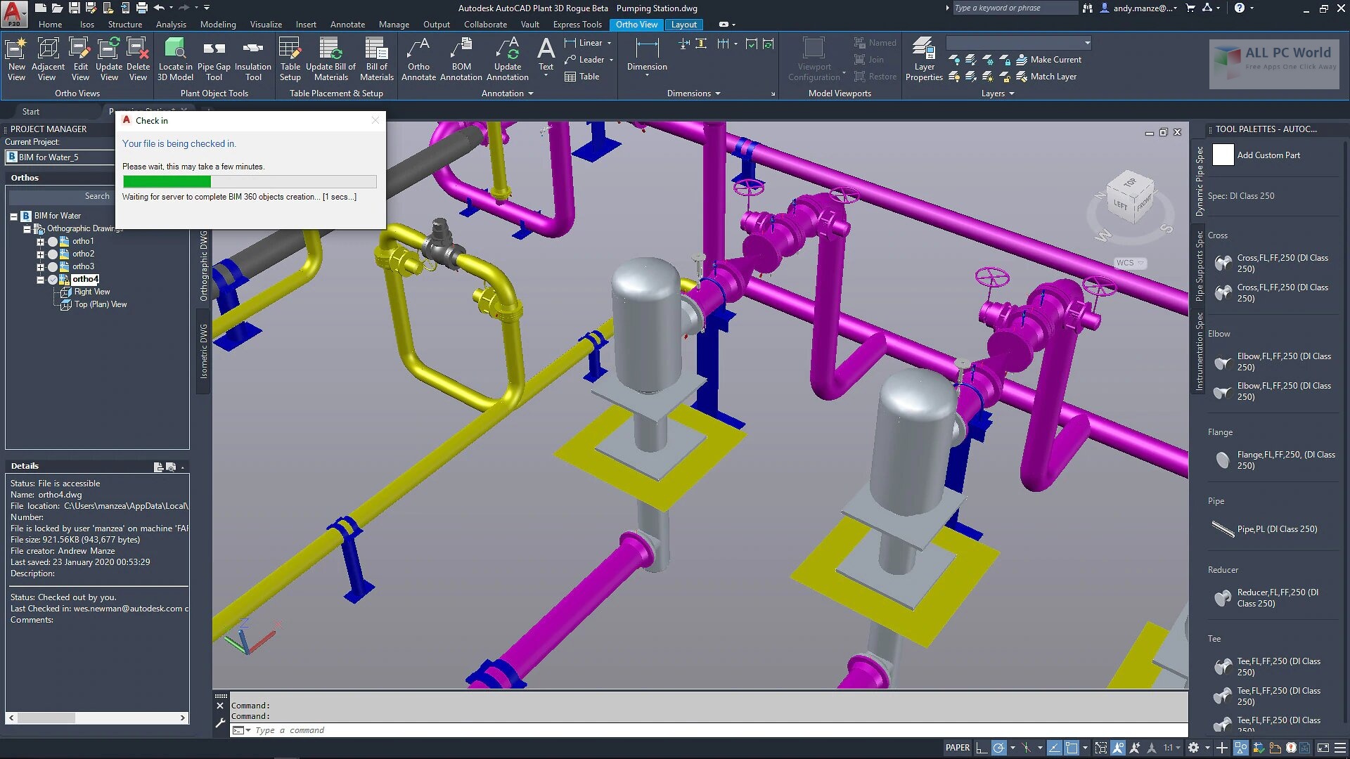
How to Create a P&ID diagram in EdrawMax Online?ĮdrawMax Online is a drawing program that is available online and as a software download. To add equipment, in the > dialog box, click equipment. The best practice is to use the size, serial number, and construction material while naming the line segment.Īlso, name each piece of equipment and instrument that is sensible and follows a convention.Įlectrical lines, pneumatic lines, and hydraulic lines should be represented by different types of broken lines and be named.Ĭlick the tab > panel >.

It is important to name each line segment for easy referencing. So, open the new document and draw the blocks of the equipment or instruments required in the design.Ĭonnect the blocks with a line according to the sequence. Before starting drawing AutoCAD p&id diagrams, you must decide the blocks that you will be using.


 0 kommentar(er)
